Desertcart purchases this item on your behalf and handles shipping, customs, and support to Spain.
โก Diagnose. Verify. Dominate your USB cables like a pro.
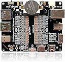
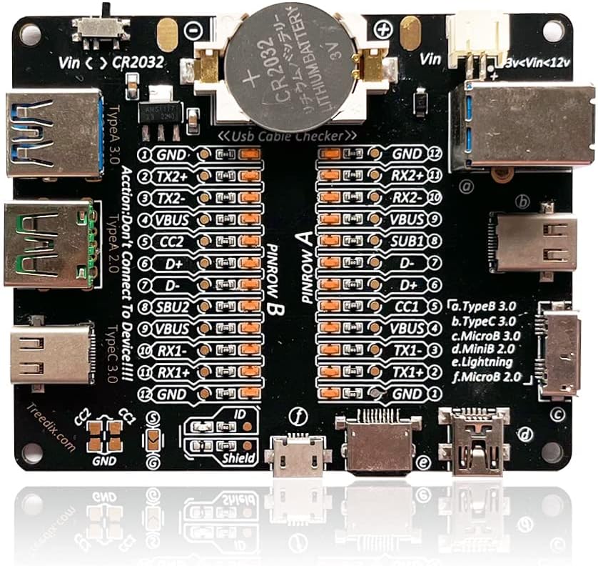
The Treedix USB Cable Data Line Test Board is a compact, professional-grade tester featuring 24 LED indicators to instantly verify the integrity of USB cables across multiple standards including Type-C, Lightning, Micro-B, and more. Powered by either a CR2032 battery or external power supply, it offers precise pin-level diagnostics to detect wiring faults and compatibility issues, helping professionals and tech enthusiasts ensure optimal cable performance and avoid counterfeit or damaged products.


| ASIN | B0BW8ZC7YD |
| Best Sellers Rank | #129,430 in Computers & Accessories ( See Top 100 in Computers & Accessories ) #14,112 in USB Cables |
| Brand | Treedix |
| Brand Name | Treedix |
| Colour | Black |
| Compatible Devices | USB devices with TypeB, TypeC, MicroB, MiniB, and Lightning connectors |
| Country of Origin | USA |
| Customer Reviews | 4.6 out of 5 stars 307 Reviews |
| Included Components | USB Cable Tester |
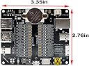
| Item Dimensions | 8.5 x 7 x 0.2 Centimeters |
| Item Weight | 0.01 Kilograms |
| Item dimensions L x W x H | 8.5 x 7 x 0.2 Centimeters |
| Manufacturer | Treedix |
| Maximum Operating Voltage | 12 Volts |
| Measurement Type | Wire Tracer |
| Minimum Operating Voltage | 3 Volts |
| Model Number | TRX5-0476 |
| Part Number | TRX5-0476 |
| Power Source | Corded Electric |
| Power Source Type | Corded Electric |
| Specification Met | CE, EN 61010-1, RoHS, UL |
| Style | USB Cable Checker |
| Style Name | USB Cable Checker |
| UPC | 741754911166 |
| Unit Count | 1.0 Count |
R**L
Excelente... si sabes algo de electrรณnica
Muy bueno, te hace un mapeo de todos los pines, sin embargo creo que la mayor utilidad es cuando sabes como interpretar las lucecitas.
M**O
One Beefy Little Guy! (Showcase of Device and Manual For Pins Included) :)
Important Warning: DO NOT use this tester to connect to live devices. Doing so could potentially damage both your devices and the tester itself. It is designed solely for testing cables as intended. --------------------------- โ Section 1 - The Review โ โข This is by far the best design I've encountered for a cheap USB cable tester. It features a straightforward circuit powered by a CR2032 battery or via a Vin pin (cable not included). Each pin of the cable connects to a corresponding light that illuminates when a cable completes the circuit. I really appreciate the broad range of compatible ports, including USB Type-A 2.0 and 3.0, Thunderbolt 3/USB Type-C 3.0 on both sides, Lightning, Micro-B 2.0 and 3.0, and Mini-B 2.0. These standards are fully backward compatible, and the inclusion of both versions ensures that this tester is 100% reliable. โข The board has two sides: "Side A" and "Side B," accommodating the reversible nature of Type-C cables. For other types such as Lightning, Micro-B, Mini-B, typically only one side will light up. Generally, you should focus on the side with the most lights illuminated; the other side can usually be disregarded, except for Lightning cables. โข One area for improvement.. It would be the documentation of expected pinouts and explanations of the different common combinations. However, this can easily be resolved with a quick Google search. Iโll share my understanding and research below. --------------------------- โ Section 2 - Hereโs a breakdown of what each of those pins means โ GND (Ground): This is the reference point for electrical signals in the circuit. It serves as the common return path for electric current. โข TX+/- (Transmit): These pins are used for data transmission. "TX+" is the positive data line, and "TX-" is the negative data line. They work together to send data signals. โข RX+/- (Receive): Similar to TX, these pins are used for receiving data. "RX+" is the positive line for incoming data, and "RX-" is the negative line. They allow the device to receive signals from another device. โข VBUS: This pin carries the main power supply voltage. It typically provides +5V to power devices or charge them. โข D+ and D-: These are the data lines used in USB connections. "D+" is the positive data line, and "D-" is the negative data line. They enable data transfer between devices. โข CC1 and CC2 (Configuration Channel): These pins are used in USB Type-C connections to determine the orientation of the connector and negotiate power delivery. They help devices communicate their capabilities to each other. โข SBU1 and SBU2 (Sideband Use): These pins can be used for additional features, such as audio or alternate modes, depending on the type of device connected. They provide extra functionality in certain situations. โข ID (Identification): This pin is used to determine the type of device connected. In certain configurations, it helps differentiate between host and peripheral roles. For example, in some USB OTG (On-The-Go) setups, the ID pin can signal whether the device should act as a host or a peripheral. โข Shield: This pin is used for grounding the shield of the cable, which helps reduce electromagnetic interference (EMI). It helps protect and improve the signal integrity by grounding any external noise that may affect data transmission. --------------------------- โ Section 3 - A valuable diagnostic tool for several reasons โ โข Signal Integrity Testing: It helps verify the quality of data transmission through the USB cable, ensuring that signals are not degraded. This is crucial for high-speed data transfer applications. โข Pin Configuration Verification: The board can confirm that all the necessary pins in the USB cable are properly connected and functioning. This is important for ensuring compatibility with devices. โข Identifying Faults and Damage: By testing various cables, you can quickly identify any faulty ones. This is helpful if you suspect that a cable is defective or if a company is providing subpar products. โข Compatibility Checks: It can help determine if a cable is compatible with specific devices, preventing the use of cables that might cause performance issues or failures. โข Preventing Scams: If you're considering purchasing cables from a vendor, using the test board can help you confirm that the cables meet advertised specifications. Then you would know to return the product for a full refund, and purchase a different cable from another vendor. This can protect you from scams where companies sell low-quality or counterfeit products. โข The Frustration Caused by USB Cables: Want to organize or discard cables, but don't know which ones are functional? You can use the USB Cable Tester Board to easily help you identify the right cables to keep.
A**R
Probably my favorite design for these USB Cable Testers.
This is probably the nicest design I've seen for these USB Cable Testers. It is a simple circuit with a CR2032 battery to energize the lines. Each pin is connected to a corresponding light, and when the circuit is completed with a cable, the light turns on. Its couldn't be a simpler design, and I love it for that! I like that you have the option to plug in just about every cable combination you could think of. It has MicroUSB, Type B, MiniUSB, Lightning, Type C, and Type A. There are some oddities, like the inclusion of both a 3.0 MicroUSB and 2.0 MicroUSB, as well as 3.0 and 2.0 Type A. These standards are fully backwards compatible, so it is confusing to me why both would be present, but it doesn't hurt anything so whatever. It does come with the ability to be wired into a power source, but it does not include cables for doing this. It came in a plain white box and a simple printout with basic operation instructions. No anti-static bag or anything, but given how simple this circuit is, it probably doesn't matter. One of the most important warnings is **DO NOT** try to use this to connect to actual devices. Best case scenario, nothing happens. Worse case scenario, it fries your stuff or itself. Use this with cables only like it is intended to be used and it will work perfectly. One thing I wish they did a bit better was showing what expected pinouts are and what the different common combinations mean, but this is easy enough to solve with a quick Google search. I'll try to offer my understanding below. Please take it all with a grain of salt, as I'm still learning myself. There are two sides on this board, "Side A" and "Side B." This is necessary because of the reversible nature of type C cables. However, with other types of cables, it is normal for only 1 side to light up. Typically (with the exception of lightning cables) you just want to look at the side with the most lights on, and you can pretty much safely ignore the other side. GND = Ground TX and RX Pairs: These pairs are what allow for USB 3 transfer speeds. One pair would allow for 5 or 10Gbps speeds depending on the encoding, and 2 pairs would allow for 10 or 20Gbps depending on the encoding. These lines are also often necessary for alt-modes, such as DisplayPort alt mode. VBUS: Voltage Bus, provides power. CC2 and CC1: These are essentially communication lines that allow the two devices plugged in at either end of the cable to communicate with each other. This line is absolutely required for PD charging. D+ and D-: Basic USB 2.0 Data lines. It is normal for these pairs to only be lit up on the B side or the A side, even with full-featured USB-C cables, as this is essentially legacy support, and additional lines are not required. SBU2 and SBU1: These lines are required for "alternate mode." This is most typically used for DisplayPort video signal, but can also sometimes be used for Thunderbolt. However, just because this lights up, it doesn't mean that Thunderbolt will necessarily work (read more about that later in the review.) ID: Used for Micro USB OTG. Normally this doesn't light up as Type A doesn't carry it. Shield: Indicates the cable is shielded. Note that this cable tester can only test electrical conductivity, and it cannot test for functionality that is not a direct result of wiring. This means things like 100W PD charging and Thunderbolt capability cannot be directly tested. This can tell you if it has the wires needed for these, but it can't tell you if the cable has an E Marker (allowing 100W) or if the signal integrity is good enough for Thunderbolt. Thunderbolt is a PCIe standard, and it is very sensitive to even the slightest of signal degradation, so something as simple as a cable being too long or not shielded well enough can make a cable straight up not work for Thunderbolt. However, this is still an incredibly useful tool, and has answered a lot of questions on some cables I had that weren't performing as expected.
J**E
i like this device I'm a little sad with the support but the device works well
I, like everyone else have a ton of cables it feels like i have millions but I know that's an extreme exaggeration. but i will say i have a lot and like you i've collected these various cables throughout the years making some of them great at the time, but now extremely outdated. The other problem is they all look a like and unless you have some kind of beautiful mind you can't remember what products they work with or what year or genteration or blah blah blah. So my friend told me about this and i purchased it and i have to say i've been going through my cables and have been surprised with what i thought were good cables and the cables that have stood the test of time!! It is easy to use and comes to you fast so you can get it really quick if you're in extreme needs!! My only problem with the item is that I'm not your hardcore computer programmer electrical engineer savant. Im very tech savvy and don't have alot of problems figuring things out if i don't know them. with the exception of this device. It gives you a ton of information, but if you don't have a background in Computer science or you're not a 8 year old prodigy hacking your elementary school to change your planned recess time, then your kind of on your own!!! Like i said there is alot of info the board gives you , but there is no guide to what that info means. I guess your just supposed to know that!! i tried reaching out to support and never got a person at all, and i even email the support address they give you and nothing. the website wasn't much help either, i couldn't even find the product on their own website??? it has a guide that tells you how to connect the cables and and what it's used for but interpreting the results. your on your own!! It would be nice if there was a little guide or map of what the different lights mean and how that corresponds to the actual cable you are testing. Meaning if i have a board where 20 of the lights are lit up what kind of cable is it? what is it capable of, and what is it not capable of as well. As it is you hook up the cables and the lights come on and that's it. like i said gifted coders and such im sure have no problems interpreting the results, but the rest of us would like a little bit of info about what we are seeing!! and since contacting support has been a bust, you're left with google to try and figure it out for yourself!!! hope this helped every that are on the fence about this product!!
T**.
Does its job perfectly, no frills
Great for sorting through my pile of USB cables. - Throw out ones with flaky or broken connections, - Mark ones that are "power only," - Mark C-C and A-C cables that are USB 2 only internally - Mark C-C and A-C cables that are USB 3 with only four wires/two differential pairs (5-10 Gbps) - Mark C-C and A-C cables that are USB 3 with all eight wires/four differential pairs (10-20 Gbps, or USB 3 + alt mode) My only complaint is that sometimes very short cables cannot make it all the way across the board. However, I've mitigated this with USB C-C cables and couplers that I separately tested and verified with this tool as having all their wires connected through to extend the length of the short cables I need to test. In practice, this has only been an issue with very short C-C and very short A-C cables; the mini and micro B ports are positioned such that even very short cables are able to easily reach those plugs. There is some slightly more advanced testing that can be done if you use a multimeter in resistance or continuity mode, along with this tester -- the tester has pads for cable shield, cable ground, and the CC1 and CC2 lines and grounds, located conveniently together to test with probes if a cable is wired with shorts or resistors between those paths. Slightly less convenient, but still very nice to have, are probe pads for each of the individual lines for both sides of the connector: this allows (e.g.) probing explicitly on those "data only" leads to see if they're being naughty and shorting D+/D- together, or have resistors between VBUS -> D+ -> GND and VBUS -> D- -> GND to falsely signal to the device that the USB port the cable is plugged into has a capability that it does not.
Trustpilot
2 weeks ago
2 months ago