

Buy anything from 5,000+ international stores. One checkout price. No surprise fees. Join 2M+ shoppers on Desertcart.
Desertcart purchases this item on your behalf and handles shipping, customs, and support to Spain.
⏳ Power your projects with precision timing — don’t let your automation lag behind!
The Walfront DC 12V Delay Relay Module offers an adjustable 0-25 second delay timer with a normally open relay and 10A current capacity. Featuring opto-coupler isolation and compatibility with both high and low-level triggers, it’s engineered for reliable, repeatable switching in industrial control, smart home automation, and electronic development projects.


| ASIN | B0761XBPT2 |
| Brand | Walfront |
| Coil Voltage | 12 Volts (DC) |
| Connector Type | Clamp |
| Contact Current Rating | 10 Amps |
| Contact Material | Silver Alloy |
| Contact Type | Normally Open |
| Country Of Origin | China |
| Current Rating | 10 Amps |
| Customer Reviews | 4.0 4.0 out of 5 stars (256) |
| Item Weight | 0.02 Kilograms |
| Manufacturer | Walfront |
| Manufacturer Part Number | Walfrontf5r0cut9y4 |
| Maximum Switching Voltage | 12 Volts |
| Minimum Switching Voltage | 12 Volts (DC) |
| Model Number | EXPSFN019067 |
| Mounting Type | DIN Rail Mount |
| Number of Terminals | 2 |
| Operating Time | 25 Seconds |
| Operation Mode | Automatic |
| Release Time | 25 Seconds |
| UPC | 663862243048 |
C**R
Worked like a charm
Followed the photos here as the instructions were t the best, but overall very happy. Works well and seems good quality.
K**V
Works Great
Great little product. I wanted a relay that would stay on after the signal had stopped. I’m using it as part of a alarm system for driveway beams.
E**O
Nice little unit, but has limitations
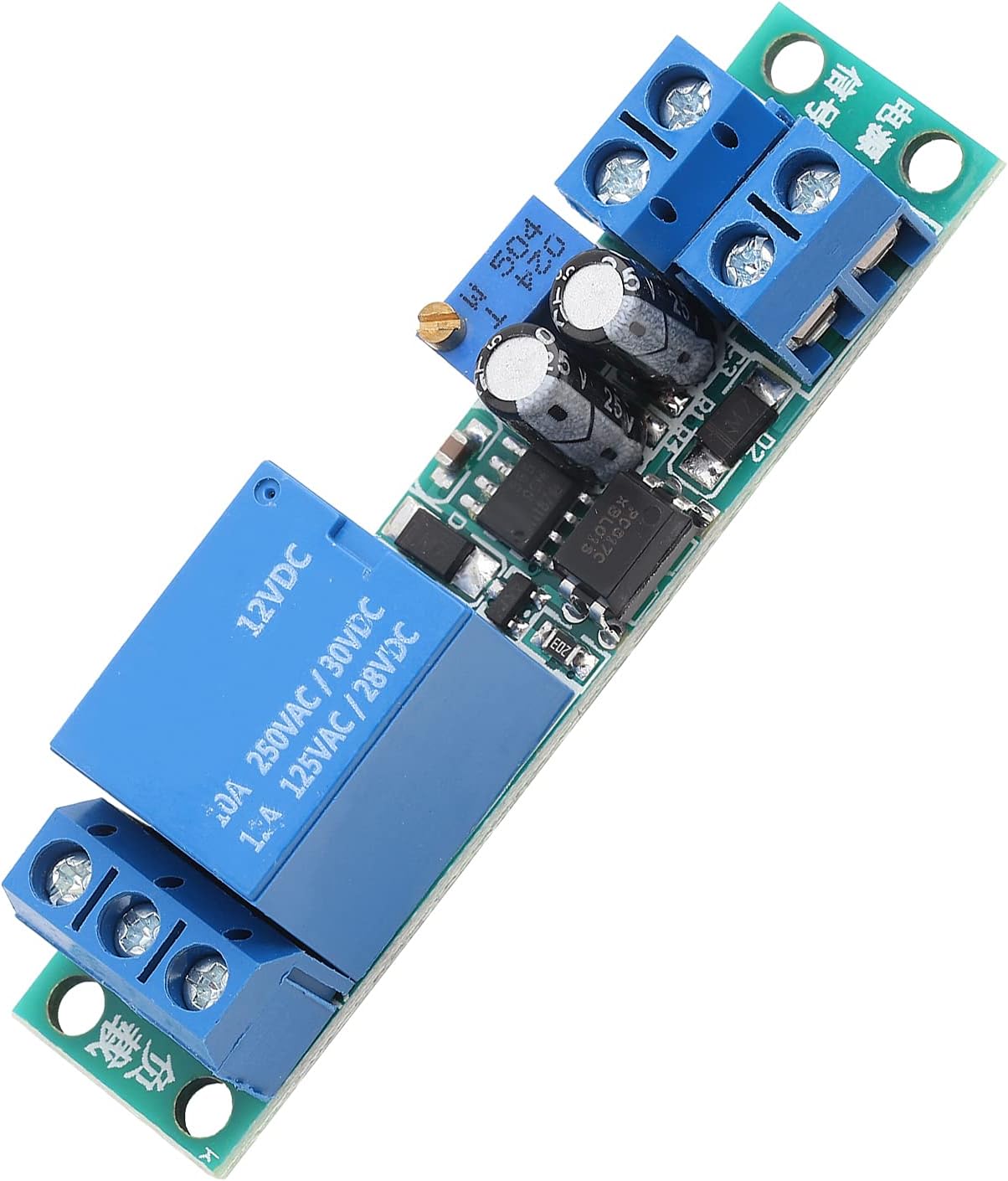
I have tested this module thoroughly and can now describe its behaviour. I tested the unit on my workbench, while connected to a 12V DC power supply (12.14V to be exact). When operating from this power supply, the current requirements are as follows: • Quiescent (standby) current : 6.5mA • Operating current (relay energised) : 26-30mA • Opto-coupler drive current : adds another 10mA I started drawing out the circuit diagram of the module, but didn't get very far. At least, I have discovered that there's a series diode for reverse-polarity protection at the 'VCC' power input terminal. The 'SVCC' signal terminal is routed to the anode of an opto-isolator via a 1k resistor, and the 'SIG' terminal is directly connected to the cathode of the same diode (see my sketch). Hence, you can elect to have the unit triggered either by the application of +12V to the 'SVCC' terminal, or by connecting the 'SIG' terminal to GND - provided you hard-wire the opposite signal terminal to the opposite power rail. I have yet to trace where the output of the opto-coupler connects, but it doesn't matter. Suffice it to say that when the opto-coupler diode is driven, the relay is IMMEDIATELY energised. Then, when current to the opto-isolator input is interrupted, the time delay starts counting down. If and when the preset time is reached, the relay de-energises. If the signal to the opto-coupler is re-applied before the delay time is reached, the 'countdown' starts again from the beginning. In summary, this module behaves as a 'run back timer'. That is: the relay energises immediately upon receiving the trigger input, and de-energises n seconds after the trigger is removed. It cannot be used as a 'delayed start' timer - which, unfortunately, is what I bought it for. (I need a timer module to delay switch-on of a Mobius dashcam until the car's power supply has stabilised after starting the engine; else the camera locks up.) One anomaly I discovered with this unit is that when connecting the permanent 12V feed to the 'VCC' terminal (while leaving the opto-coupler input disconnected), there's about a 50/50 chance whether the unit starts up with the relay energised. In my mind, this is erroneous behaviour. This means that you can't switch the system on/off via the 'VCC' input and expect a reliable outcome. Logically, if the signal input(s) are not driven, then the unit should NEVER start up with the relay energised. Thankfully, if it does start up with the relay energised, it will de-energise once the preset time delay has expired and will then work correctly from that point onwards. Finally, a word about the time delay potentiometer setting. I discovered that rotating the trim pot clockwise DECREASES the time delay - this is counter-intuitive. Also, if you turn the pot too far clockwise, it disables the device altogether, and the relay will not operate. EVER! Perhaps this is the condition that some reviewers have experienced, and declared their units to be non-functional.
A**A
No instructions but doable
I am no expert in electronics. It took me a couple of hours but I managed wiring it so that the light goes off after being activated by a push-button. Check vid and pictures, have fun!
L**I
Works, but not as advertised
I think the adjustment pot is faulty (constantly the same resistance. Therefore I cannot change from the 120 sec. But it does work as expected. Just no adjustable time
R**S
DC 12V Delay Relay Module Board 0-25second Adjustable Timer Relay
Like other interested parties have commented - NO INSTRUCTIONS. So I have uploaded a picture diagram on how to wire-up, hope it helps. Otherwise ALL is good and works perfectly - very happy with this purchase.
A**R
Did not have wiring diagram no instructions
There was no instruction or wiring diagram had to spend time working it out
M**.
Doesn't work
With 12v connected to the inputs there is no output for any duration no matter how the pot is adjusted. Complete waste of money.
A**K
se trata de un circuito con un relé muy versátil. Se puede realizar para cualquier circuito que precise de un temporizador (modificándolo a tu necesidad) Concretamente, yo lo he utilizado para alimentar durante “un segundo” una cerradura eléctrica de puerta, que me daba problemas y se me quemaba la bobina con el circuito original porque a veces se quedaba pillada. Con este circuito, conectado a la bobina de la cerradura, sólo le entra la tensión un segundo, aunque el circuito original se quede “pillado” que es lo que me sucedía. No hace falta decir que lo que conecto a la cerradura es el contacto NO del relé salida. también advierto que hay que tener un minimo de conocimiento sobre lo que se está haciendo, aunque no hay que ser ingeniero. Imágenes: Foto 1 alimentación del dispositivo . Foto 2 puentes realizados para minimizar el espacio. La salida para mi cerradura el común y el NO (normalmente abierto) así de simple.
S**N
Fungerar ej
P**E
Qualité - prix au top
D**7
LE REGLAGE DU TEMPS NE FONCTIONNE PAS.
D**R
einwandfrei - perfekt
Trustpilot
1 month ago
1 month ago